Beam Load Capacities Chart
Search capacity by parameter(s)
| Family | Beam height | Length | Deflection | Part Number | 18 Digit Code | Capacity (LBS) |
|---|---|---|---|---|---|---|
| {{product.family}} | {{product.beam}} | {{product.length}} | {{(product.length / 180).toFixed(2)}}" | {{product.partNumber}} | {{product.sku}} | {{product.capacity}} |
Please remember:
- Capacities are per the 2012 RMI and 2001 AISI specifications.
- Interlake Mecalux beams over 126”L require bracing to prevent buckling.
- Beams longer than 90” that support decking must be tied together to prevent spreading (IK025B crossbar).
- Loading to be uniformly distributed over the length of the beam.
- Values shown reflect the capacity of the beams based on the lesser of its strength in bending, or L/180 deflection criteria.
- Load capacities are for uniformly distributed product load plus dead load per pair of beams (dead load = weight of beams).
- Capacities are valid for static load only.
- These capacities assume that all component parts are: (1) Manufactured by Interlake Mecalux. (2) In good condition. (3) Properly installed.
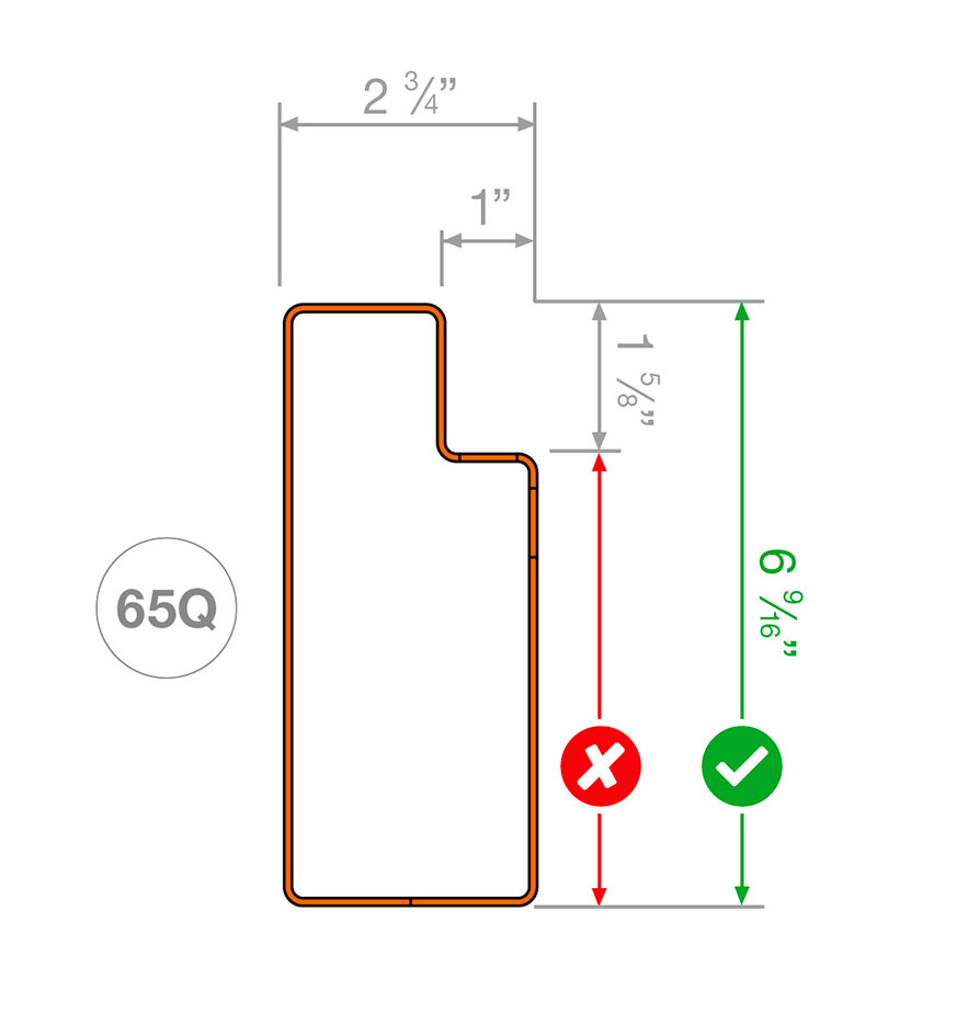
Make sure you measure the beam height as shown in the figure below:

About Deflection Specification:
When a qualified rack design engineer determines the specifications for a pallet support beam, they calculate the maximum allowable deflection, or bowing. This limit is specified in Section 5.3 of RMI's ANSI MH16.1-2012: Specification for the Design, Testing, and Utilization of Industrial Steel Storage Racks.
The deflection limit is the horizontal lenght of the beam divided by 180, or 0.55% of the clear distance between the columns.
Uniformly Distributed Load vs Point Loads:
- Avoid placing loads with feet or runners that create concentrated pressure points on the beams.
- Ensure the load has a uniform distribution of weight or mass across its entire surface area.
- Make sure the load is symmetrically placed on the shelf in both depth and width.
- Do not use undersized loads for the shelf. If smaller loads are placed toward the center of the beam rather than near the frame, it increases stress and deflection on the beam.
Why is the RMI Deflection formula L/180 for Selective Roll Formed Beams?
The L/180 deflection limit was established years ago as an aesthetic standard, based on what is generally considered an acceptable visual level of deflection.
Significant deflection can understandably cause concern for those working around the racks.
It's important to note that some people expect no deflection at all and may be alarmed when they see any.
However, designing beams to exhibit minimal deflection would be costly and would require beams with a much greater depth relative to their span.
How can I measure Beam Deflection?
The simplest way to get a reasonably accurate measurement of beam deflection is by stretching a rope or string across the bay, positioned just below the beam, at the height that the beam is welded to its end-plate connectors. Make sure the string is taut and adjust it at both ends so that the distance between the string and the bottom of the beam is equal at each end. Mark the center of the beam. Place evenly distributed loads on the beam, both front-to-back and side-to-side, ensuring the weights are uniform so the front and rear beams are loaded equally.
Next, measure the distance from the bottom of the beam to the string at the midpoint of the beam. Subtract this value from the distance measured from the bottom of the beam to the string at the ends. This difference is the beam deflection. Keep in mind that, like any method, this process involves some margin of error.
The advantage of using the string is that it eliminates errors that can occur if measurements are taken from the floor, especially if the floor is not level. It also removes any downward displacement from the beam’s connections, ensuring the deflection measurement reflects only the bowing caused by the load on the beam. There are also more advanced methods, such as using lasers, to measure deflection more precisely.
